Ignition Principles of Operation-
Most small engines are equipped with a magneto ignition system to create spark for combustion to take place. A magneto is capable of creating in excess of 20000 Volts of electricity at the spark plug electrode tip, without any outside supply of electricity, such as a battery. In this article, we will cover what types of magneto ignition there are, as well as how they actually work, and the science behind it.
Here is an example of different magnetos-
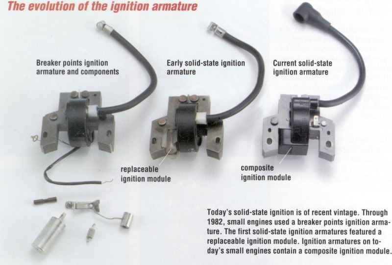
There are two types of magneto ignition, one that uses points and condenser, and solid state. Breaker points are essentially obsolete at this point, as most manufacturers have been using solid-state ignition for the past 25 years or so.
The biggest reason for the elimination of points is that points begin to wear and deteriorate as soon as they are put into service. They require constant maintenance and adjustment. Over the years, many manufacturers produced kits that eliminated the points, and turned the ignition into a solid-state setup. The most recognizable name for most is the Briggs Magnetron kits that were very popular, and still are for aficionados of older equipment.
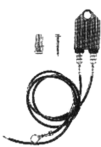
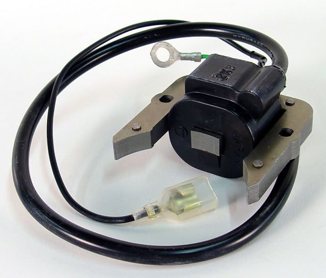
Here is an example of an external mount solid state kit. It is not the Magnetron kit, of which I could not find a picture.
The points and condenser act as a switch to cause the ignition coil to send the spark through the spark plug wire to the the spark plug. This can still be seen in an older car distributor.
Solid-state electronic components are what we use today. They replace the mechanical action of the points with an electronic version of the same thing, called a transistor.
Solid-state magnetos consist of few parts, which is the beauty of them. They have the circuit board, windings, an armature, and they are sealed with epoxy to protect them from the elements and vibration.
Now that we have discussed the different types of ignition systems, we should discuss the components that make it work.
The first is the flywheel. The flywheel will have a magnet embedded in it, and there is usually only one. Most of the time, you see two pieces of metal, but the magnet is U-shaped, and it has a north and south pole, which is essential for the magneto to work properly. On a side note, the flywheel is also responsible for cooling in a small engine. They have wings on them that intake air from the outside and displace it underneath the shrouding and on to the cylinder. It is for this reason that keeping mice nests out from under the shrouding is important.
Here is an example of a flywheel-
Here we need to dive into some basic science, in order to fully understand how these systems work.
The first thing to talk about here is magnets. I am sure most of us here have used, or played with magnets. Magnets have a magnetic field. Magnets also have north and south poles, just like Earth, which is also a magnet.
The Earth's magnetic field is what makes a compass work, and what causes the "Northern Lights" at the North Pole. (The Northern Lights are also known as Aurora Borealis (Astronomy is also a hobby of mine))
You may remember from Physics class about magnetism. A magnetic field consists of what are called "lines of flux". Maybe you remember what every teacher does with iron filings, to demonstrate the lines of flux- but here is a drawing-

The lines of flux are invisible, but the iron filings prove they exist. These lines are 3-dimensional and surround the magnet.
These lines of flux will interact with any conductor they come near. A conductor is anything that will transmit electricity.
When a magnet is moved near a conductor, an electrical current is produced in said conductor. This is called electro-magnetic conduction. The amount of current produced is directly proportional to the strength of the magnet and the speed it is moving.
When a magnet moves on a conductor, the electrical current produced is pushing back against the magnet. This happens because the electrical current produced is of opposite polarity of the magnet used to generate it. (See the Law of the Conservation of Energy, and Newton's third law) This interaction is known as eddy currents, which will be important to know later in this article.
This electro-magnetic induction was discovered by Micheal Faraday (who is probably known better from the SI unit of capacitance, the Farad...) and another important discovery that lies within his theory is that if a copper coil of wire is exposed to a changing magnetic field, that is, the field changes from north to south or vice versa, an electric current is induced in the wire. An experiment some might remember from high school is the alnico magnet in the varnish coated copper wire tube, with a galvanometer hooked to the wire. My high school physics teacher showed us this, but he was an old teacher, and I don't know what technology has brought to the classroom in the past 5 years, or if other schools were the same as mine.
Lets summarize briefly so that we can apply what information is presented here to magneto ignition systems.
Magnets have invisible magnetic fields, known as magnetic lines of flux. (High school Physics)
When a magnet moves by a conductor, the lines of flux interact with the conductor, and this interaction induces electricity. (Faraday)
This shows us how magnetism and electricity can interact. Before we can apply these theories totally, however, we must first discuss a bit about magneto construction.
Most magnetos are similar in construction. A steel or soft iron core, usually U-shaped is make of thin stampings, laminated together, called the armature. They [the laminations] are slightly insulated from each other by a thin coating of oxide. This is where eddy currents come into play. If the core were solid, it would have strong eddy currents that would cause heat and make the coil less efficient than with the laminations. The eddy currents are reduced by using laminations that are slightly insulated from one another.
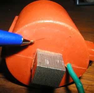
Here is an example of the laminations. This is actually a coil from a Continental aircraft engine, but the construction is the same.
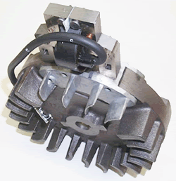
And a magneto off of a small engine-
This laminated core transfers the magnetic lines of flux through the windings without actually being magnetized itself.
Wrapped around the core are two windings of wire, called a primary, and a secondary winding. The primary is the low voltage side of the coil. It usually has about 200 turns of coated copper wire wound tightly around the armature. One end is grounded, and the other end is connected to the solid state controller, or the breaker points.
The secondary winding has as many as 20000 turns of a very fine wire, and is wrapped around the primary. It is the high voltage side. One end is grounded, and the other is connected to the spark plug wire.
Now that we know how this coil is constructed, we can further discuss the operation.
The Magneto mounts close to the flywheel. There is an air gap between the legs of the armature and the flywheel. This is to ensure that there is a transition of polarity, which is essential if you remember Faraday's theory discussed earlier. As the flywheel spins past the armature, the magnetic flux lines travel up the legs of the armature. Because both the primary and secondary windings are wrapped around legs of the armature, an electric current is induced by the lines of flux cutting through the windings. As the flywheel magnet moves by the legs of the armature, the polarity of the magnetic field changes direction.
The current builds until either the points open or the solid-state switch, usually a transistor opens the circuit and the circuit is no longer complete. Current can't flow if the circuit is not closed.
When the circuit is opened, the concentrated magnetic field in the windings collapses, and this process creates high voltage, 15-20,000 Volts, depending upon the design, and this current is able to jump the spark plug gap under up to 150 PSI of compression, to ground, to complete the circuit.
The secondary windings are wrapped around the primary, so that when the magnetic field is building, reversing, and collapsing, a step-up in voltage occurs in the secondary windings.
By using a laminated armature, a primary and a secondary winding, the magnetic lines of flux can be directed and amplified to ultimately give us up to a 20,000 volt spark. This is happening on every revolution of the flywheel, so at 12000RPM, it would be happening 200 times a second.
Now that we have a firm foundation on how the ignition event happens, we can look further into the subject.
It is worth mentioning that magneto ignition is not the only type of ignition used on small engines. There are a good number that also use a traditional battery ignition, with an automotive style coil and condenser. They also use points to collapse the field, or there are some that use a capacitor to discharge, or collapse the field. The operation is the same, but like someone said, there is more than one way to skin a cat.
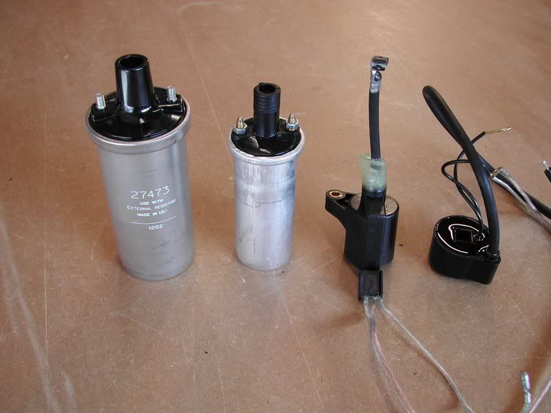
Here is an example of different battery ignition coils-
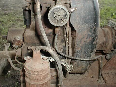
As well as a pic with it installed on an engine-
Now that we know how the ignition event happens, we can now talk about when it needs to happen. This is called timing, and will be the subject of the next article.
As always, if you have any questions, please feel free to ask.
Andrew